What Audio DSP Actually Does (and Why a CPU Can't Just Do It Instead)
Audio DSP handles the repetitive math behind filtering, fast Fourier transforms, and echo cancellation. These are fixed-point operations running millions of times per second with strict timing requirements. A general-purpose CPU can do them, but it burns cycles on instruction decoding and branch prediction that a DSP core dedicates to multiply-accumulate operations. The difference shows up in power consumption and determinism. You get guaranteed loop timing on a DSP. A preemptive OS scheduler can't promise that, and the gap matters more than most people expect when you're trying to hit a hard deadline on every single sample.
Consider voice activity detection. A low-power DSP implementation on a Cortex-M0+ can run a 32-sample moving-average energy detector plus spectral flatness threshold at under 500 microwatts. That's from Analog Devices App Note AN-1349. Try doing that with a CPU core waking from sleep to process audio buffers. The overhead of context switching and peripheral polling kills your power budget.
If I'm being honest, most of the CPU-based audio processing I've seen in consumer gear cuts corners on algorithm efficiency to hit price points, then compensates with a bigger battery. For always-on applications like smart speakers or security cameras with audio analytics, you need dedicated silicon.
That brings us to chip choices. Not all DSP architectures are equal, and the trade-offs between fixed-function and programmable cores matter more than marketing suggests. We'll get into that next.
TI TMS320 vs ADI SHARC: Chip-Level Spec Comparison for Audio Work
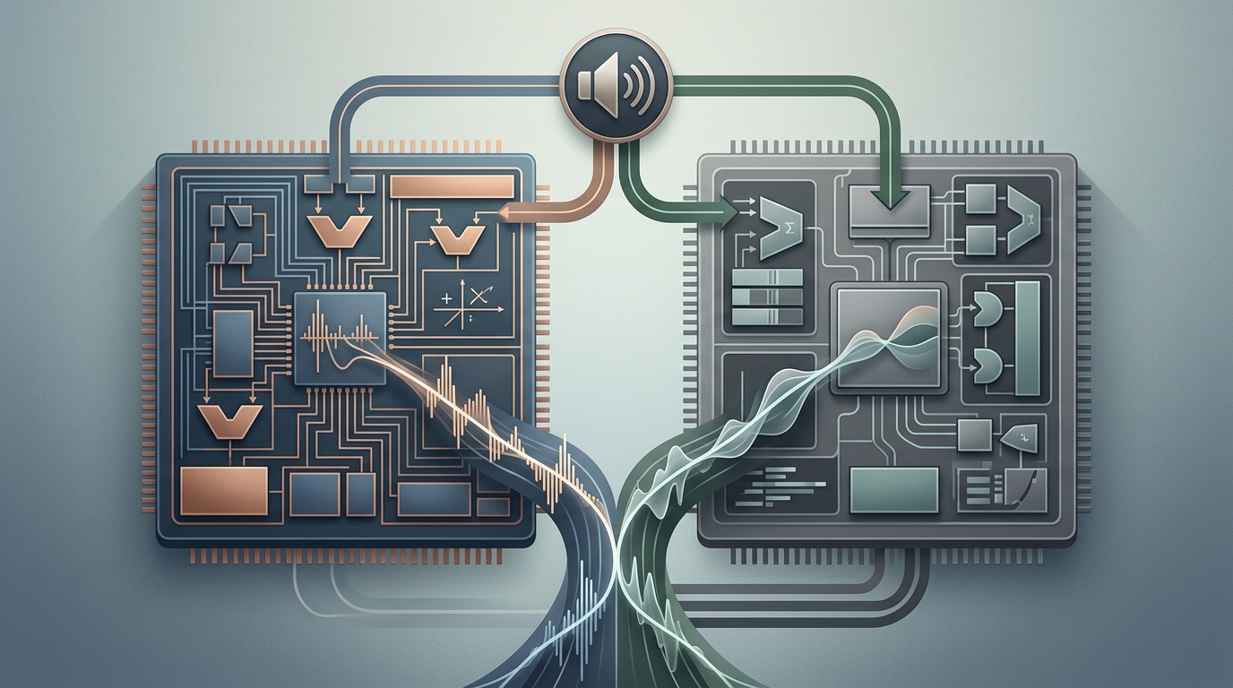
So let's compare the silicon that actually runs the algorithms. Per Analog Devices SHARC+ product page, the SHARC+ family is the professional audio DSP standard, used inside Bose QC noise-cancelling processing, dbx EQ processors, and Waves plugins. That's a serious pedigree. The TI TMS320 family has its own strongholds, especially in embedded control and some consumer audio, but the SHARC's floating-point architecture and memory bandwidth give it a clear advantage for complex, multi-channel audio processing.
The core difference is in the architecture and how it handles math. SHARC processors are designed for maximum I/O and memory access bandwidth, with all instructions executing in a single cycle. This balance is critical for sustained performance in real-time applications. The latest SHARC+ cores, like those in the ADSP-2156x and ADSP-2159x families, reach up to 1 GHz per core with tightly coupled SRAM that can be accessed in a single cycle.
For a direct hardware comparison, look at the key specs.
| Feature | ADI SHARC+ (ADSP-2156x/2159x) | TI TMS320C66x (Typical) |
| :--- | :--- | :--- |
| Core Architecture | 32/40/64-bit Floating-Point SIMD | 32/64-bit Fixed-Point / VLIW |
| Max Core Clock | 1 GHz (single), 2 GHz aggregate (dual) | ~1.25 GHz |
| On-Chip L1 SRAM | 5 Mb (640 KB) per core | 32-64 KB per core (typical) |
| On-Chip L2 SRAM | Up to 8 Mb (1 MB) | 1-2 MB (typical) |
| Key Audio Peripheral | Digital Audio Interface (DAI) w/ routing | Multichannel Audio Serial Port (McASP) |
| Hardware Accelerator | Enhanced FIR/IIR offload engines | Viterbi/ Turbo coprocessor |
The SHARC's massive on-chip memory is a game changer for audio. You can keep entire filter delay lines and processing kernels in L1, avoiding the latency hit of going off-chip. A SHARC might cost more per chip, but it can save you an external memory part and the board complexity that comes with it.
Choosing between them is less about peak FLOPS and more about your signal chain's bottlenecks. Count your channels, add up the taps in your longest filter chain, and check whether the delay lines fit in on-chip SRAM. That arithmetic picks the chip more reliably than any benchmark chart.
The raw math is only half the story. How these chips move data from the ADC, through the DSP core, and out to the DAC defines the system's real capability. We'll break down that signal chain next.
How the Audio DSP Signal Chain Works: From ADC to Output
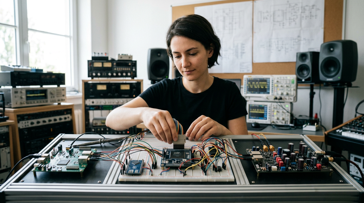
So let's trace that chain. It starts with an analog signal, maybe from a microphone. That signal hits an analog-to-digital converter, an ADC. The ADC's job is twofold: sample the signal at a fixed rate and quantize each sample's amplitude into a digital number. The Shannon-Nyquist theorem sets the rules here. You have to sample at least twice the highest frequency you care about, otherwise you get aliasing, those ghost frequencies that wreck your data. Most current audio ADCs use a sigma-delta architecture, oversampling at a super high rate and then using digital filtering to produce a clean PCM stream. It's a clever workaround for getting high resolution without insane component costs.
That digital stream now lands in the processor. This could be a dedicated DSP chip, an FPGA, or even a general-purpose CPU. Meanwhile, the chosen hardware applies the algorithms, equalization, compression, whatever the system needs. All the same, the processed digital data then heads to a digital-to-analog converter, a DAC. Again, sigma-delta designs dominate here, taking the PCM stream and converting it back into a smooth analog waveform ready for an amplifier and speaker. That's the full chain. It's not complicated once you see it laid out, but each stage depends on the one before it doing its job cleanly.
The whole chain is less about the individual blocks and more about the quality of the filters and the integrity of the clocking between them. A cheap ADC with a poorly designed antialias filter will poison the entire process before it even begins.
That processed analog output is where we hit the limits of what DSP can fix. Next, we'll look at why active noise cancellation starts to fail right around 1 kHz. That's a narrow frequency band. The physics behind it constrain what even well designed feedback loops can do once wavelengths drop short enough that the error microphone and the speaker are no longer sampling the same acoustic space.
Active Noise Cancellation: Why ANC Fails Above 1 kHz
That 1 kHz mark isn't arbitrary. It's where the math behind active noise cancellation starts to break down against physics. Sound wavelengths shorten dramatically above that point. A 1 kHz tone has a wavelength around 13 inches. By 4 kHz, it's just over 3 inches. When the distance between your external microphone and the driver creating the anti-noise wave is measured in millimeters, timing errors become catastrophic. The processor simply can't generate a perfect inverse in the required microseconds.
Bose/Sony/Apple public teardowns data shows the DSPs handling ANC are specialized for this exact problem. A Bose QC 35 uses an Analog Devices SHARC processor, while Apple's AirPods Pro rely on their custom H2 chip. These are designed for the low-frequency, predictable waveforms of engine rumble or HVAC hum. Above 1 kHz, sounds become transient and complex. A speech consonant or a key click changes too fast for the adaptive filter to converge. The system ends up chasing its own tail. That often creates a faint hiss or hollow artifact that wasn't in the original signal. That's why passive isolation, the physical seal of an ear cup, does the real work up high.
I've stopped paying much attention to the stated high-frequency cancellation specs on data sheets. The real world performance gap between 500 Hz and 2 kHz is massive. A system rated for 30 dB of reduction might only manage 10 dB in that range, if you're lucky. Judge an ANC product by its low-frequency attenuation and its passive seal, because those are the two numbers that survive contact with reality.
That's where common failure modes in the field really begin.
Common Failure Modes in the Field
Audio DSP systems rarely die in spectacular ways. They degrade, and the degradation almost always traces back to the boundaries between domains: clock domains, power domains, and the analog-digital boundary itself.
Clocking is the first place I look. When the ADC and DAC run from different clock sources, even a tiny frequency mismatch means buffer slips, and buffer slips mean periodic clicks that no amount of filtering removes. Sample rate converters exist precisely to bridge mismatched clock domains, which is why serious multi-source audio chips build them in hardware. If a system clicks once every few minutes like clockwork, it's clockwork.
Power integrity is the second. A shared supply rail lets amplifier load transients modulate the converter's reference, and that shows up as noise correlated with the program material, the kind that vanishes on the bench with a clean lab supply. Ground loops between separately powered boxes add the classic mains hum. Neither is a DSP bug, but the DSP gets blamed for both.
The third is the buffer math itself. Real-time audio dies by underrun: if the processing chain can't finish every block before the DAC needs it, you get dropouts. The temptation is to grow the buffers, which fixes the dropout and quietly adds latency until a live monitoring path becomes unusable. Fixing it properly means profiling the worst-case path, not the average.
Knowing where things break down lets you focus your bench time there. We'll cover the questions that come up most in the section below.
Frequently Asked Questions
Do I actually need a DSP chip, or can a CPU handle my audio? For offline processing, a CPU is fine. For always-on or hard real-time work, wake-word detection, ANC, live monitoring, dedicated DSP silicon wins on power and determinism. The AN-1349 figure above tells the story: hundreds of microwatts for an always-listening detector on a DSP core versus a CPU that pays context-switch overhead every time it wakes.
Why do premium headphones still leak high-frequency noise? Because ANC is physics-limited above roughly 1 kHz, where wavelengths get short enough that microsecond timing errors ruin the anti-noise phase alignment. The ear-cup seal does the real work up there. If high-frequency isolation matters to you, judge the passive seal first and the ANC spec second.
What sample rate should my system run at? Match your delivery target. 48 kHz is the professional and broadcast standard because it divides evenly into video frame rates; 44.1 kHz is the consumer legacy standard from the CD era. Running higher than your delivery rate buys processing headroom, at the cost of proportionally more MACs per second through every filter in the chain.
What's a sigma-delta converter and why does every audio chip use one? It oversamples at a very high rate with a coarse quantizer, then uses digital filtering and decimation to trade that excess rate for resolution. The payoff is high effective resolution from cheap analog parts, and a gentler analog anti-aliasing requirement, which is exactly the cost profile consumer audio needs.
My system clicks or hums and the code looks right. What now? Check the boundaries, not the algorithm. Periodic clicks point to mismatched ADC/DAC clocks slipping a buffer. Hum at mains frequency points to a ground loop between separately powered units. Noise that tracks the music points to power-rail coupling into a converter reference. All three masquerade as software bugs and none of them are.